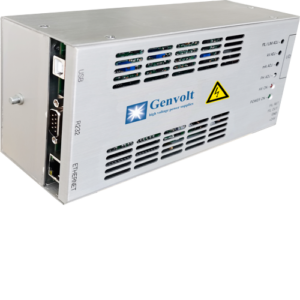

Electron beam applications & X-Ray.
EB04-220Vac-N1200-120-F30-B400
Output voltage: 120 kV
Output current: 10mA
Filament voltage: 30 V
Filament current: 20 A
Grid bias voltage: – 400 V
Grid bias current: 20mA
This machine contains grid bias of +400V. Positive and negative grid bias switchable.
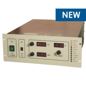
There is a red emergency stop button, green power switch and status indicator on the front panel.
The high voltage can be shut down immediately by pressing the red emergency stop button. Rotate the button clockwise, then the button will reset and cancel interlock for high voltage. The green power switch is used to switch on/off main power source. The status indicator shows the working status of the power switch, constant voltage or current status, overvoltage alarm, overcurrent alarm for filament, chain reaction and discharging prompt.

(Front Panel A)

(Front Panel B)
There are three interfaces on the rear panel of the power supply, J1, J2 and J3.
J1 is for DB9, 485 port, which is used to communicate with the computer to control the operating mode.
J2 is DB50, analogue signal transmission port for connection with remote controller.
J3 is RJ45 port and is not available for this machine.

(Rear Control A)
High power output on rear panel
Fuse
Mains AC input
Grounding bolt
Three signal interfaces: RS485, DB50 and RJ45
INTERLOCK pillar

(Rear Control B)
Wiring is as shown in the images below. Make sure that all wiring is well grounded.
Short circuit of interlock pillar.
Do not cover the fan.
Make sure there is a secure connection in place for the high voltage cable and the communication cable.

(Wiring A)

(Wiring B)
Three-core cable, industrial standard HV connector R24 socket and corresponding cable connectors are integrated. Maximum filament current is up to 20A. Output of three-core cable: one for common, one for filament, and one for grid bias. Especially suitable for applications with large filament current.

All output parameters can have an analog value from 0V to 10V for remote setting.
High voltage 0V to 10V refers to 0kV to -120 kV.
Filament voltage 0V to 10V refers to 0A to 20A.
Grid bias 0V to 10V refers to 0V to -400V.
7U to 11U .
Aluminium alloy shell.

This power supply contains high voltages and power. Contact with the output may result in fatal injury. It should only be used and maintained by trained personnel.
Before opening the power supply, please check following:
1. Whether the power supply and its environment is clean and dry;
2. Whether there are irrelevant items nearby the output or load of high voltage;
3. Make sure the return current from the load is well grounded via the grounding bolt at the back.
| Pin | Name | Note | Pin | Name | Note |
| 1 | BIAS NEG FBK | Feedback for negative grid bias | 26 | NC | undefined |
| 2 | FIL I FBK | Feedback for filament current | 27 | HV ERR | High voltage error |
| 3 | mA FBK | Feedback for beam current | 28 | BIAS ERR | Grid bias error |
| 4 | HV FBK | High voltage feedback | 29 | HV INV OV TEMP | Overheat of high voltage inverter |
| 5 | BIAS POS FBK | Positive grid bias feedback | 30 | FIL INV OV TEMP | Overheat of filament inverter |
| 6 | BIAS DEM PLC | PLC negative grid bias setting | 31 | SPARK | Discharging |
| 7 | FIL DEM PLC | PLC filament setting | 32 | CONST mA | Constant current |
| 8 | mA DEM PLC | PLC beam current setting | 33 | NC | undefined |
| 9 | HV DEM PLC | PLC high voltage setting | 34 | NC | undefined |
| 10 | AGND | Analog signal ground | 35 | HV ON PLC | PLC high voltage on |
| 11 | FIL ERR | Filament error | 36 | NEG BIAS ON PLC | PLC negative grid bias on |
| 12 | HV C/L | Overcurrent of high voltage inverter | 37 | FIL ON PLC | PLC filament on |
| 13 | FIL C/L | Overcurrent of filament inverter | 38 | POS BIAS ON PLC | PLC positive grid bias on |
| 14 | PFC OV HV | PFC overvoltage | 39 | BEAM CLOP ON PLC | PLC close beam current on |
| 15 | CONST HV | Constant voltage | 40 | DGND | Signal ground |
| 16 | INTERLOCK | Interlock | 41 | DGND | Signal ground |
| 17 | DGND | Signal ground | 42 | 15 | + 15V |
| 18 | NC | undefined | 43 | AGND | Analog signal ground |
| 19 | NC | undefined | 44 | NC | undefined |
| 20 | NC | undefined | 45 | NC | undefined |
| 21 | NC | undefined | 46 | NC | undefined |
| 22 | NC | undefined | 47 | NC | undefined |
| 23 | NC | undefined | 48 | NC | undefined |
| 24 | NC | undefined | 49 | NC | undefined |
| 25 | NC | undefined | 50 | NC | undefined |
Note: All error signals are low level. Refer to DGND.
PLC set signal is 0- 10Vdc, where 0 refers to the maximum. Refer to AGND.
For all switching signals, 0v refers to on, suspend or high level refers to off. Refer to DGND.