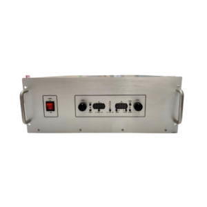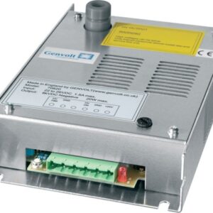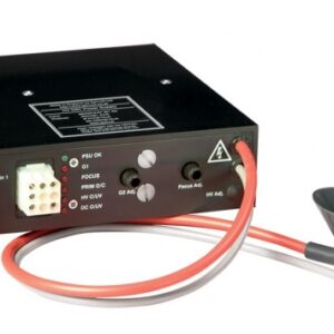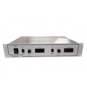
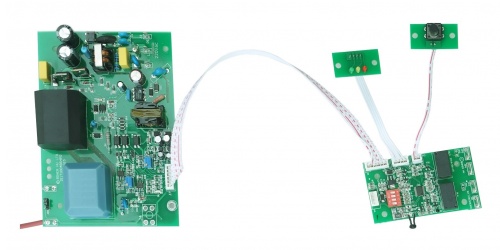

AF02C range of high voltage power supply standard specifications
| No. | Model | Input voltage | Power | Output voltage | Polarity | Note |
|---|---|---|---|---|---|---|
| 1 | AF02-220VAC-P20-6K6 | 220VAC±10% | 5 – 30W | 5 – 8kV | Positive | Airflow sensor, arc detection and protection, rinse time settings and warnings. |
| 2 | AF02-220VAC-P20- 8/4K |
220VAC±10% | 5 – 30W | Ionizer: 8kV Collector: 4kV |
Positive |
Note: For requirements other than those specified, please contact the factory for further information.
| No. | Features | Specifications |
|---|---|---|
| 1 | Appearance | a. Power supply PCB (inc. HV stack), dimensions: 144mm x 101mm x 60mm. Control PCB (inc. LED and reset button), dimensions: 118mm x 43mm x 17mm. b. Power supply PCB input 220VAC, using 2.8 x0 .7 tabs. Control PCB passive signals output, using 6.3 x 0.7 tabs. c. Lead out high voltage cable. Bottom lead out available, exterior cable length 250mm. d. No sign of corrosion or oxidation on solder joints on PCBs (i.e. shining surface), solder joints are lower than 8mm height. e. Lacquered protection on both sides of PCBs and component pins. f. PCB thickness 1.6mm. |
| 2 | Power input | 220VAC input on the Power Supply PCB. Green LED on the display PCB turns on when running normally. |
| 3 | Power-off protection | PCB providing power to ion chamber and switches off after running for a while. 5 seconds later, touching the high voltage laminate by high voltage probe without any high voltage indications on DVM. |
| 4 | Airflow detection | In the normal working condition: a. When airflow<1.2m/s, the sensor responds and determines the result in 30 seconds, HV output off, green LED off. b. When airflow≥1.2m/s, the sensor responds and determines the result in 30 seconds, HV output on, green LED on. c. Jumper links available to disable the airflow sensor on the Power Supply PCB when necessary. 6.3 x 0.7 tabs available for external connection. |
| 5 | Fault protection | When the power supply experiences a continuous arc on load for 10s, the output will be switched off momentarily for 10s, green LED turns off. After which, it will be restored automatically, green LED turns on. When the continuous arc on load for 10s has occurred for 5 times, the output will be switched off, green LED turns off, red LED turns on. Restart to redeem normal operating. Power-off time should be no longer than 5s. |
| 6 | Rinse time | There are 6 durations to select from for rinse alarm time (per every 600 hours). When the time is up, rinse LED on (yellow). The flashing rate of the green LED on the Control PCB indicates the set duration. Factory default setting is 3600 hours |
| 7 | Rinse alarm | When the rinse time is up, rinse LED on (yellow). The HV output will be switched off after 360 hours, without resetting the rinse reset button. Green LED turns off. Restart the power supply, it will not switch to normal operation mode until the reset button is pressed. |
| 8 | Reset | When yellow rinse LED is on, reset the alarm, rinse LED turns off and rinse time set as zero. |
| 9 | Dry contact signal output |
When red fault LED is on, relay JP6 on the Control PCB closes and sends a passive signal to building management system. When yellow rinse LED is on, relay JP5 on the Control PCB closes and sends a passive signal to building management system. |
The continuous operation of the power supply is guaranteed under below circumstances:
Environment temperature: -10℃ to 50℃.
Relative humidity: non-condensation when less than 80%,/p>
Connect the 6.3mm tabs J5 and J6 on the Power Supply PCB, or link pin 2 and 3 on JP9 on the Power
Supply PCB, to disable airflow sensor (to work normally when there is no wind). Otherwise enable
the airflow detection.
Set rinse alarm time by adjusting 1st, 2nd and 3rd (4th is not in use) position on the red toggle switch on the Control PCB. There are 6 durations to select from for rinse alarm time (per every 600 hours),as shown in the table below:
| No | Toggle switch status | Time (hour) | Time (Day) |
|---|---|---|---|
| 1 | 001 | 600 | 25 |
| 2 | 010 | 1200 | 50 |
| 3 | 011 | 1800 | 75 |
| 4 | 100 | 2400 | 100 |
| 5 | 101 | 3000 | 125 |
| 6 | 110 | 3600 | 150 |
Note: Toggle switch ON = 0, OFF = 1.
The flashing rate of the green LED on the Control PCB indicates the set duration.
The power supply will start working according to the connections stated above with 220VAC power
on.